


Posted to News on 30th Jan 2014, 00:00
ISO 14119 for interlocking devices associated with guards has arrived
The new standard "ISO 14119:2013 Safety of machinery - Interlocking devices associated with guards - Principles for design and selection" has arrived and will replace EN 1088 within 18 months. David Collier CMSE, Business Development Manager at Pilz UK and chairperson of the Machinery Safety Alliance, explains what it will mean for machine builders.
>Although there is an 18 month transition from EN 1088, machine builders who design safety gate systems will be at an advantage if they aim to comply with the new ISO 14119 immediately. Technologies exist which can overcome challenges, like fault masking, and when deployed can provide added peace of mind as well as compliance with the more exacting requirements of this new standard.
>In contrast to the previous standard EN 1088, ISO 14119 considers additional technologies such as RFID or electromagnetic guard locking, classifies interlocking switches and regulates more clearly the specifications for installing guards. These regulations are particularly significant with regard to protection against guard manipulation, also known as defeating of guards.
>ISO 14119 will replace all national standards on this subject and will be valid worldwide. Formally this signifies a huge step forwards: the old standard was purely European, whereas the new standard is published by ISO. There are too many technical differences between EN 1088 and ISO 14119 to be detailed here, but there follows a taste of some of these differences.
>Types of interlocking device: The first point is that ISO 14119 now takes into account many technologies now available which weren't when ISO 1088 was first published. The table below shows an overview of the interlocking types and a helpful cross reference to the examples in the annex of the standard. Types 3 and 4 (non-contact devices, uncoded and coded) did not exist in EN 1088, and examples of their use are given in Annex C and D of ISO 14119.
>Levels of coding: A coded actuator is defined as one which is specially designed (for example by shape, magnetically, or radio frequency RFID) to actuate a certain position switch. Levels of coding to prevent defeat are defined as: low level (for which 1 to 9 variations in code are available); medium level (for which 10 to 1000 variations in code are available); and high level (for which more than 1000 variations are available). High level covers uniquely coded RFID systems; medium covers trapped key systems and some limited RFID systems; low covers magnetic reed switch types and re-teachable RFID types.
>Guard locking: The type of guard locking is expanded from power to lock or power to release, to include bistable locks where power can be applied to lock and release a solenoid guard switch. It also considers the circumstances under which the use of electromagnetic locks (just the use of electromagnetic force without tongue) is allowed for machine safety (for example taking into account the distance to the hazard, the stopping time in the event of power loss, monitoring the holding force, providing clear indication when forced entry has been attempted). Locking for personnel protection (against injury) and for process protection (against interruption) are differentiated.
>Whilst it is the task of the machine C-standard or the designer to determine the required holding force for an interlocked guard, and it is the responsibility of the interlock manufacturer to specify the interlock's strength to resist static action force, Annex A Table I.1 of ISO 14119 offers guidance on typical static action forces based upon the direction of opening force, posture of the operator and type of operator grip (for example single or bi-manual).
>Defeating of interlocking devices: Section 7 states that "The machine shall be designed in such a way that it minimises the motivation for defeating the interlocking devices" and goes on to stipulate "The interlocking device shall provide the minimum possible interference with activities during operation and other phases of machine life, in order to reduce any incentive to defeat it." Various measures are described to realise these requirements (for example preventing access to the interlocking device, preventing the use of substitute actuators through levels of coding, integration of defeat monitoring by cyclic testing). The implication is that it is increasingly the designer's responsibility to ensure that interlocked guards can't be defeated, which in turn requires the designer to understand how the machine will be used at every stage of its life (production, maintenance, setting, cleaning and so on).
>The use of fault exclusions: The use of fault exclusions has long been covered in EN 62061 (max SIL 2), TR ISO 23849 (PLd) and now also in EN ISO 13849-2 (Annex D.8 a single mechanical point of failure (the tongue or cam) cannot be fault excluded for PLe). This limitation to PLd for fault exclusions now appears in ISO 14119. In other words to achieve PLe, using at least two devices is mandatory; it is one reason we are seeing more non-contact devices being used for PLe since they have no single mechanical point of failure. Interestingly though, the locking function, although dependent upon a single mechanical channel (the tongue) is allowed to perform up to PLe with the proviso that it is defined as locking up to a maximum stated extraction force (which the manufacturer, not the user, can demonstrate through repeatable, certifiable tests).
>Testing infrequently used guards: Some interlocked guards aren't opened often, so forced testing by manual functional opening and closing at regular intervals is required to check for possible accumulated faults. ISO 14119 specifies for PLe a monthly test and for PLd a 12 monthly test. This is important, even in dual channel systems, because faults can only be revealed by placing a demand on the guards. It is recommended that the control system of a machine demands these tests at the required intervals, for example by visual display unit or signal lamp. The control system should monitor the tests and stop the machine if the test is omitted or fails.
>Fault masking: Picture a number of interlocked guards connected in one circuit back to a safety relay. A fault (for example a short circuit across one of a pair of normally closed contacts in an interlock switch due to a contact weld or moisture) can develop in one of the guards, which will be detected by the safety relay only when the faulty guard is opened. The safety relay will see one of the channels open but not the other (it expects to see both open) so the safety relay will both shut the associated part of the machine down and it will "lock out" because it has registered the fault. When the operator closes the guard, the fault remains registered in the safety relay which prevents a reset and restart.
>In many cases the operator will not investigate this further - he may try to open and close the guard again, to no avail, following which he may try to open and close other nearby guards and as if by magic, the fault is cleared because one of the other healthy interlock switches causes simultaneous opening of its pair of contacts which the relay recognises as a healthy state and the machine can be restarted. But, unbeknownst to the operator, the safety system has accumulated a now-undetected fault which has actually degraded its performance. All it will take is one more fault and the safety function will be lost. The phenomenon is known as "fault masking".
>Historically the practice of series-wired safety switches has arisen because it saved money on cabling and safety relays, and because such dual channel wiring translated to Category of 3 of the now-withdrawn standard EN 954-1 (for more than one switch in series, EN 954-1 degraded Category 4 to Category 3). Category 3 lives on in the standard EN ISO 13849-1 in which clause 6.2.6 requires that for Category 3 to apply specific conditions must be met which include: a single fault must not lead to a loss of the safety function, that an accumulation of undetected faults can lead to the loss of the safety function, and importantly as an addition over and above EN 954-1's requirements that at least 60% of faults have to be detected in a diagnosis mechanism (DC = low). The ability of a system to detect 60% of dangerous faults can be impacted by fault masking which can dramatically reduce the Diagnostic Coverage and consequently the Performance Level.
>It was expected that fault masking would be covered in detail ISO 14119, and it is - to a point. Here is the exact text from the final draft of EN ISO 14119, in section '8.6 Logical series connection of interlocking devices':
>"Logical series connection of interlocking devices means for NC contacts wired in series or for NO contacts wired in parallel. When interlocking devices with redundant contacts are logically connected in series the detection of a single fault can be masked by the actuation of any interlocking device logically connected in series with the defective interlocking device to the safety related control system.
>"It is foreseeable that during the fault finding (troubleshooting) by the operator one of the guards whose interlocking devices are logically connected in series with the defective interlocking device will be actuated. In that case the fault will be masked and the effect on the diagnostic coverage value shall be considered.
>"For a series connection the maximum DC (see ISO 13849-1 or IEC 62061) should be considered.
>NOTE: A technical report dealing with the logical serial connection of devices is in preparation."
>The real detail of how many devices can be serially connected is the subject of a forthcoming technical report, "ISO/PDTR 24119 - Safety of machinery - Evaluation of fault masking serial connection of guard interlocking devices with potential free contacts." It is currently under committee review, with an expectation that it will be available quite soon. In simple terms if we have more than one frequently opened guard (once per hour) the level of Diagnostic Coverage falls to zero which in EN ISO 13849-1 results in a max PLc. It remains to be seen exactly what ISO/TR 14119 has to say about the maximum PL achievable where several infrequently operated guards are connected but it is very likely to be PLd where careful analysis is possible (for example of the number of guards, the type of switches, type of wiring, distance between guards, and accessibility of guards) otherwise it is more likely to be PLc. It is definitely not possible to achieve PLe with more than one guard connected in series, at least not when using volt-free based interlock switch technology.
>There are three industrially available options on how to overcome fault masking:
>
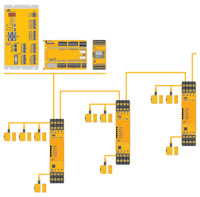
- Individual wiring or localised zoning:Don't connect or at least limit the number of volt-free, interlocking devices in series, wire them individually to individual safety relays on individual inputs on safety controllers or zone small groups together.
- Intelligent interlocking devices:Use devices which are not based upon volt-free contacts, rather based on self-monitoring transistorised outputs (known as OSSDs) - these are typically found on RFID contactless switches, which can detect faults within themselves. These can be connected in series and maintain the highest levels of diagnostics, to achieve PLe. PSENcode switches (RFID guard position monitoring devices with self-monitoring OSSDs)
- Safe Distributed I/O systems: Distributing interlocks (and other devices like light curtains, emergency stops, two hand controls, etc) across the machine can be done safely using a failsafe network - effectively the network addresses devices connected in a chain around a machine and can distinguish between all inputs and test for faults (for example through the use of test pulses). There are various solutions to this based generally upon nodes where devices are either "addressed" or given a specific input identity on the network (generally using software).
>As a final comment ,ISO 14119:2013 provides machine builders and users with much wider scope to use a broader range of technologies when interlocking guards, it also places more responsibility on the designer to prevent foreseeable, deliberate bypassing of guards, and it will change the way in which guard interlocking devices are connected across machines. Pilz GmbH was involved in formulating the draft standard.